Nov 13, 2026
Linear motion sits behind a lot of modern industrial equipment. Automated production lines, CNC machinery, material handling systems and positioning devices all need controlled movement. There are several ways to push a machine part along a straight path, and rack and pinion is one of the common.
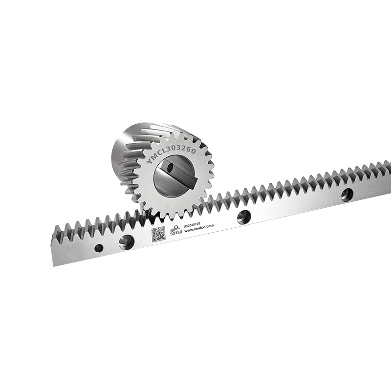
The idea is easy to picture. A round gear meshes with a straight toothed bar, and as the gear turns, rotary motion becomes linear movement. The layout is simple, but the system still relies on several parts doing their jobs together.
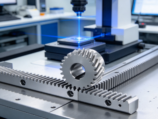
The rack sets the straight path. The pinion turns rotation into travel. Bearings, mounting structures, motors, guides and lubrication then back up the transmission. How these parts are designed and installed affects movement quality, positioning, service life and stability.
Knowing what each component does helps equipment designers and manufacturers choose a drive system that suits the working conditions.
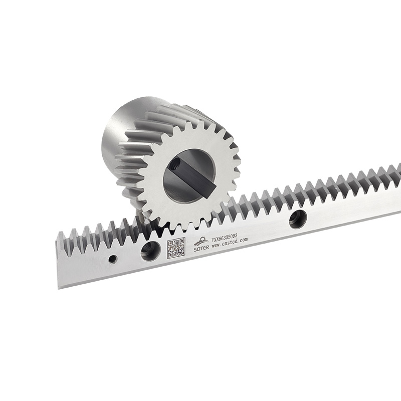
A linear rack and pinion drive is a mechanical transmission that produces straight-line movement. It has two core parts: a toothed rack and a circular gear called the pinion. Their teeth mesh.
As the pinion rotates, its teeth push on the rack teeth. If the rack is fixed, the pinion and whatever is attached to it travel along the rack. If the pinion stays in place, the rack moves instead. Which one moves depends on the equipment design.
Turning rotation into straight-line motion makes the system handy for machines that must travel along a path under control. An electric motor or another drive source supplies the rotation, and the rack and pinion pass that movement to the machine.
A typical system may include:
Configurations vary. Some are purely mechanical and quite simple, while others add components for motion control and monitoring. The right choice depends on the machine's structure, load, travel range and operating environment.
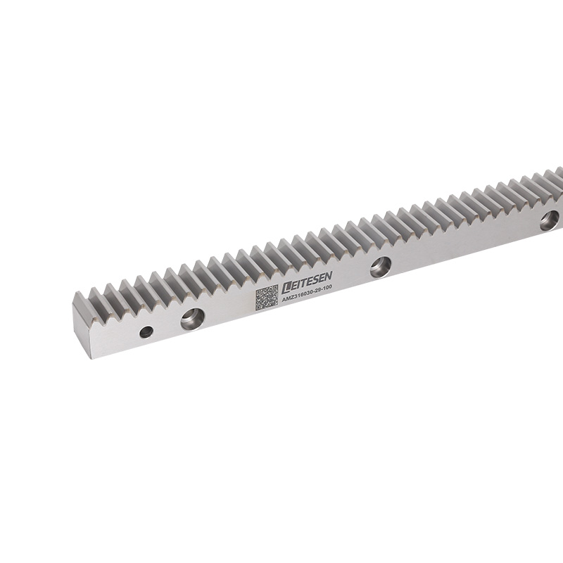
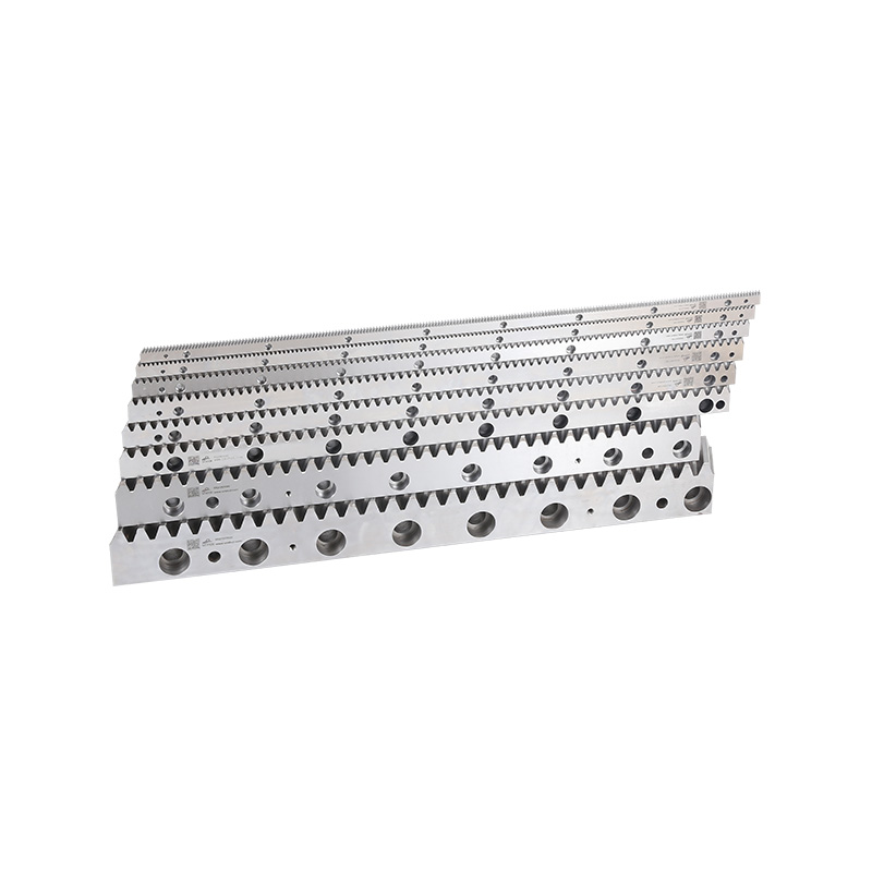
The rack is the straight toothed part. It defines the path along which the pinion travels or drives another machine part, and its teeth let rotational force produce linear travel.
Racks are usually metal, since they take repeated contact and mechanical loads. Shape, tooth design, surface condition and mounting position all affect how smoothly the system runs.
A rack can be mounted straight onto the machine frame or onto a separate support structure. Either way, the mounting surface needs to be stable. An uneven or misaligned rack means the pinion won't engage consistently.
Rack length follows the travel distance. Where a long range is needed, several rack sections are joined end to end. The joints need careful alignment, because poorly matched ones interrupt gear engagement and make movement uneven.
The rack's main functions are:
So the rack isn't just a passive metal bar. Its mounting, tooth condition and relationship with the pinion directly shape how the transmission behaves.
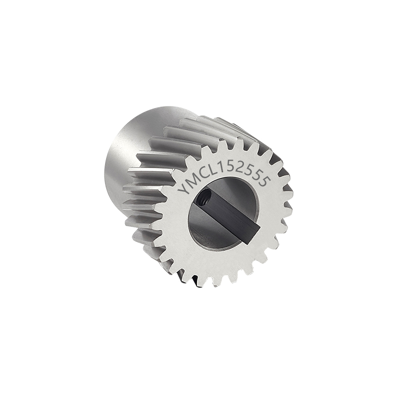
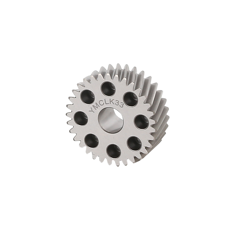
The pinion is the round gear that meshes with the rack. A motor or other drive source feeds it rotation, and as it turns, its teeth push against the rack teeth to create linear movement.
Pinion design has to match the rack. The two tooth shapes must work together so contact stays stable. If they're incompatible, expect noise, vibration, uneven movement or heavy wear.
The pinion normally sits on a shaft that carries rotation from the drive source. Depending on the machine, a coupling or gearbox may sit between motor and pinion.
Pinion size and tooth arrangement also set how motor rotation translates into linear travel. Designers take that relationship into account when deciding how the drive should move.
Several factors shape pinion performance:
| Factor | Influence on the System |
|---|---|
| Tooth design | Affects contact between the pinion and rack |
| Material | Influences strength and resistance to wear |
| Surface condition | Affects friction and contact behavior |
| Installation position | Determines how the pinion engages with the rack |
| Shaft connection | Transfers rotational movement to the gear |
| Maintenance condition | Influences long-term operating stability |
The pinion has to stay correctly positioned while running. If its support allows too much play, the contact between gear and rack shifts. Tooth contact becomes uneven, and the connected equipment moves less cleanly.
The motor provides the energy that moves the system. Electric motors are common in industry because they integrate easily with automated control equipment.
Motor rotation goes to the pinion, and the pinion drives the rack. Motor choice depends on the movement needed, the load, the machine design and the expected operating conditions.
A gearbox may sit between motor and pinion. It alters the relationship between motor rotation and output movement, and it can help the drive deliver the force an application needs.
Not every system needs a separate gearbox. Some connect the motor to the pinion through a coupling or another transmission structure, depending on the required motion and available space.
Treat the motor and gearbox as one drive arrangement. A motor that doesn't suit the application may struggle to move the load smoothly, and an unsuitable gearbox can hurt the system's response and behavior.
When choosing these parts, manufacturers often consider:
The links between motor, gearbox, shaft and pinion deserve attention too. A poorly aligned connection adds vibration or extra stress, so proper mounting and installation keep the drive stable.
Bearings and linear guides both support movement, though they do different jobs. Each helps keep moving components where they should be.
Bearings carry rotating parts such as the pinion shaft. They let the shaft turn while limiting unwanted movement. If the bearing setup is unsuitable or worn, the shaft can become unstable, which affects how the pinion meshes with the rack.
The bearing support structure must also withstand the forces produced in operation. A steady shaft position keeps gear tooth contact consistent.
Linear guides do something else. They support the moving assembly and steer it along a straight path. In many machines the rack and pinion supplies the driving force, while the linear guide system controls direction.
That distinction matters. Don't assume the rack and pinion alone guides the moving part. Separate guides may be needed to carry the load and prevent unwanted movement.
The relationship looks like this:
| Component | Main Function |
|---|---|
| Bearings | Support rotating shafts and reduce unwanted movement |
| Linear guides | Guide the moving assembly along a straight path |
| Guide rails | Provide the fixed support path for the moving elements |
| Moving blocks | Connect the moving assembly to the guide system |
| Mounting base | Supports the rack, guides, and related components |
Incorrectly installed guides can leave the moving assembly misaligned. That changes the pinion's position relative to the rack, which can bring uneven contact, vibration and poorer movement quality.
For that reason, the rack, pinion, bearings and linear guides should be designed together.
The mounting structure holds the main components in their intended positions. It can include the machine frame, base plate, brackets, support blocks and fasteners.
These parts may look plain, yet they matter a lot. The rack and linear guides need stable mounting surfaces, and the motor and pinion need suitable support to keep their relative positions.
If the structure flexes or shifts under load, rack and pinion alignment can change. Tooth contact suffers, movement turns uneven, and a weak support may add vibration.
Installation quality counts as much as part design. Mount the rack along the intended travel path, align joined sections carefully and make sure fastening points give stable support.
Pay attention to these installation details:
The mounting structure should also suit the surrounding machine. Dust, moisture, vibration and temperature swings can affect support parts, so designers need to weigh these when choosing materials and protection.
Rack and pinion teeth touch during operation, and repeated contact means friction. Without enough lubrication, wear goes up. A lubrication system keeps contact conditions suitable and the transmission smooth.
Depending on the application, lubricant may be applied by hand or automatically. Manual lubrication relies on operators sticking to a regular schedule. Automatic systems deliver lubricant at planned intervals and cut down on repeated manual work.
The better method depends on system design, environment and maintenance plan. Dust and other contaminants can degrade lubricant, and too much lubricant may trap unwanted particles, so follow the equipment manufacturer's guidance on amount and method.
Maintenance goes beyond lubrication. Operators should also inspect rack and pinion teeth, mounting fasteners, bearings and guide components.
Common maintenance tasks include:
Strange noise is often an early warning. Poor alignment, too little lubricant, damaged teeth or loose mounting parts could all be behind it. Investigate changes in sound or movement instead of writing them off as normal.
A clear maintenance routine lets manufacturers spot wear before it causes wider damage, and it makes equipment behavior more predictable.
The mechanical parts create the physical movement. Sensors and control devices manage how it happens. In automated machinery they can monitor position, control travel and coordinate motion with other equipment.
A position sensor reports where a moving assembly is. That information can go to a control system, which uses it to manage the machine's movement.
Limit switches mark the ends of a travel path. They can stop movement or trigger another action when a moving part reaches a set position.
Some systems also use feedback devices on the motor. These let the controller watch motor movement and adjust operation to suit the machine's needs.
Common control components include:
| Component | Purpose |
|---|---|
| Position sensors | Detect or monitor the location of moving parts |
| Limit switches | Identify travel boundaries |
| Motor controllers | Manage motor operation |
| Feedback devices | Provide movement information to the control system |
| Control units | Coordinate the drive system with other machine functions |
What you choose depends on the application. A simple machine may get by with basic limit switches, while an automated production system may need detailed position feedback and coordination.
Sensors also need proper installation and protection. Wrong positioning can give unreliable signals, and dust, moisture, vibration and electrical interference may affect them depending on the environment.
Design the mechanical and control systems as connected parts of one machine. Reliable movement needs both the physical transmission components and the devices that manage them.
Related Products

If you have cooperation intention, please leave a message for us or use the following ways to contact us.We will reply to you as soon as possible and provide you with more sincere service, thank you.
Production
QR Code
Call Us :
+86-13758631128
E-mail :
sttc@cnstcd.com
Add :
31 piazza road, ruoheng town, wenling city, taizhou city, zhejiang province, China.
Copyright © by Zhejiang Soter Transmission Technology Co., Ltd. Rights Reserved.

China Rack And Pinion For Sale

 English
 中文简体
 Español
 русский