Nov 06, 2026
Industrial machines often have to move heavy loads along a straight line. A cutting head crosses a work surface. A lifting platform travels between positions. A machine component on an automated line follows a set route. These movements look simple from outside, but each one relies on a system that passes force along and guides motion.
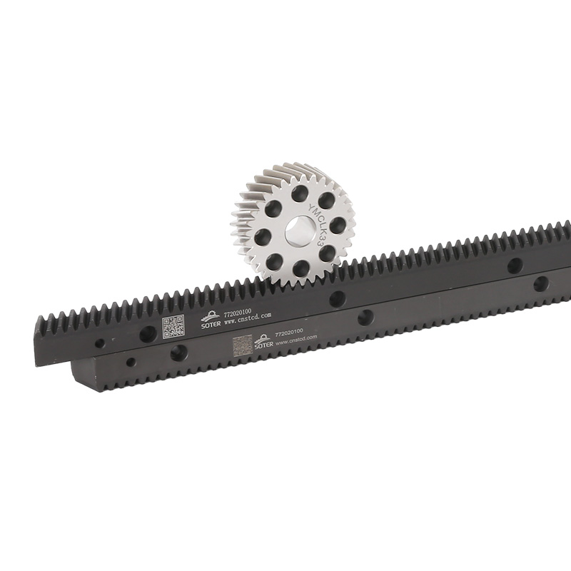
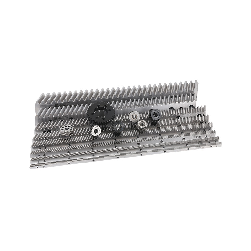
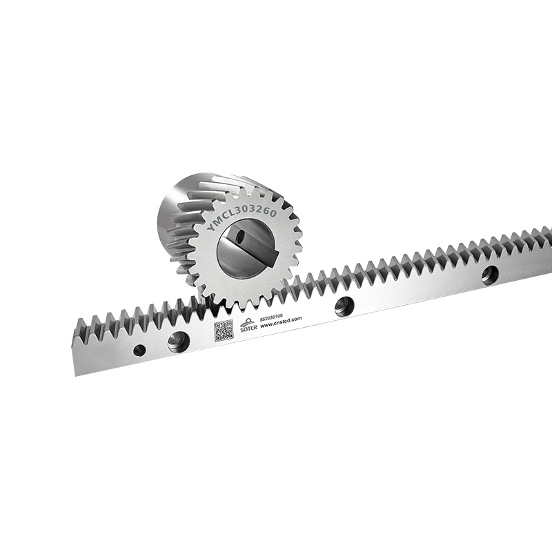
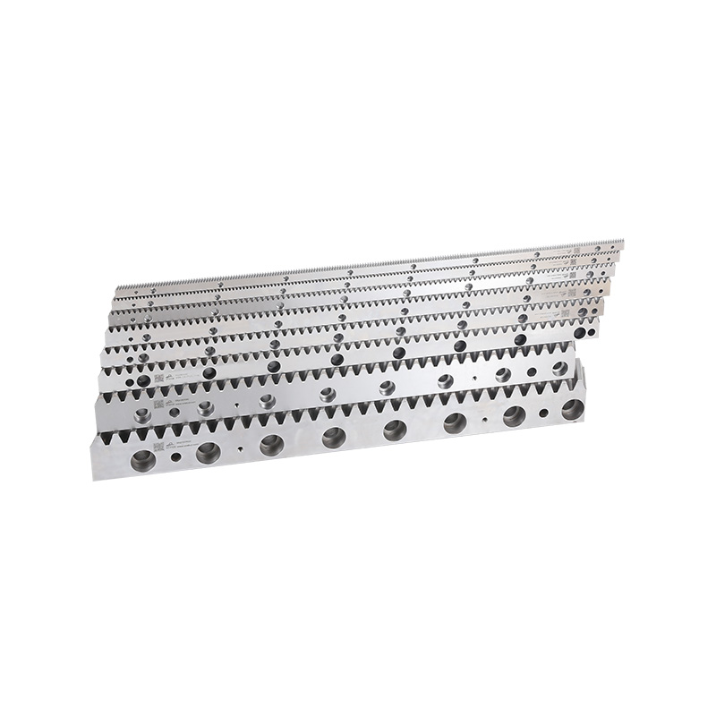
A rack and pinion system is one way to get that movement. It has two main parts: a straight toothed bar called the rack, and a round toothed gear called the pinion. When the pinion turns, its teeth mesh with the rack's teeth and push the rack in a straight line.
The principle is easy to grasp, yet it shows up in a wide range of machinery. You'll find it in machine tools, automated equipment, lifting devices, and material handling systems. The design can also be adapted to different movement needs.
Knowing how it works explains why manufacturers choose it, how its parts interact, and what affects it during daily production.
An industrial rack and pinion system is a mechanical drive that converts rotary motion into linear motion. Rotary motion is a part turning around an axis. Linear motion is a part traveling along a straight path.
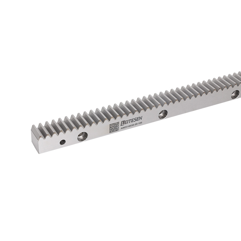
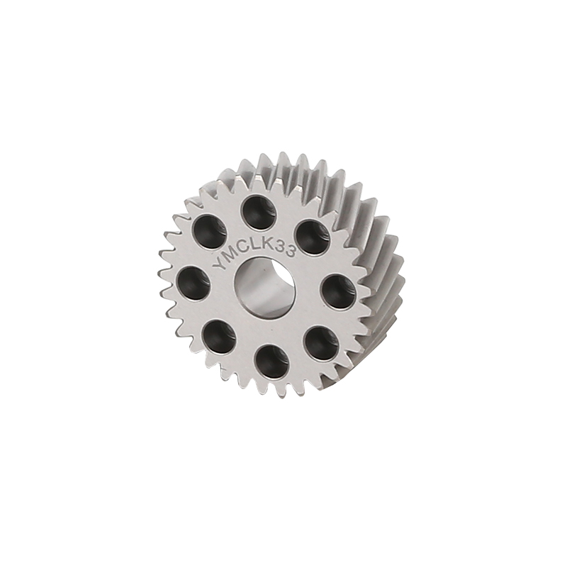
The rack is a straight bar with teeth along its length. The pinion is a circular gear with matching teeth. As the pinion turns, its teeth press against the rack teeth, and the rack moves forward or backward depending on the direction of rotation.
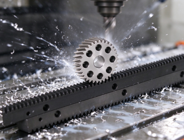
This gives a direct link between turning and straight-line travel. There's no belt or screw in between. The rack and pinion engage each other directly.
The system normally sits inside a larger machine. A motor or other drive source supplies the turning force, and the pinion passes it to the rack. Guides, supports, and mounting structures keep everything aligned. The rack may carry a machine table, carriage, platform, or another part that must travel along a set path.
Designs differ by application. Some move light machine components, while others are built into equipment that carries heavy loads. The basic principle stays the same even when the surrounding structure changes.
Movement starts when a drive source turns the pinion. Its teeth engage the rack teeth, and as the gear rotates, each tooth passes through the contact area and pushes the rack along.
The distance traveled is tied to the pinion's geometry and how far it turns. One full turn gives a repeatable amount of linear travel, as long as the parts stay properly engaged.
Direction is just as simple. Turn the pinion one way and the rack moves one way. Reverse the pinion and the rack reverses. That suits machines that must go back and forth during repeated work cycles.
Picture a carriage that has to travel along a long work surface. The rack is fixed to the machine frame, and the pinion is mounted on the carriage. As the pinion turns, it walks along the fixed rack and carries the carriage with it. In another layout, the pinion stays put and the rack slides through the machine.
Both layouts use the same principle. The choice depends on the machine's structure, the available space, the load arrangement, and the travel path you need.
The system doesn't create motion on its own. It transfers movement from a motor or other source and turns it into controlled linear travel the machine can use.
A rack and pinion drive has several parts that work together. The rack and pinion form the main transmission pair. The other components keep the movement controlled.
| Component | Main function |
|---|---|
| Rack | Provides a straight toothed path for linear movement. |
| Pinion | Engages with the rack and transfers rotational force. |
| Drive source | Supplies the movement needed to rotate the pinion. |
| Mounting structure | Holds the components in their intended positions. |
| Guide system | Keeps the moving assembly on its required path. |
| Bearings and supports | Help rotating parts operate with controlled movement. |
| Lubrication arrangement | Reduces friction and limits wear between contacting surfaces. |
| Control system | Coordinates movement, direction, and stopping where required. |
Each part affects the whole assembly. A rack may have good teeth, but poor mounting can stop it engaging consistently. A well-installed pinion can still cause unwanted movement if the guides let the carriage drift off its path.
The drive source matters too. The motor must deliver movement that suits the machine's work. The control system can adjust direction and speed, and position feedback helps automated equipment reach a specified spot.
Not every system uses the same supporting parts. A manually operated mechanism may be quite simple. An automated production machine may add controls, sensors, protective covers, and monitoring devices.
The point is that you can't judge the rack and pinion alone. Performance depends on the surrounding structure and on how the complete system is assembled.
A rack and pinion system usually repeats the same sequence of movement. Details vary by machine, but the general flow is easy to follow.
Movement begins. A motor or other drive starts turning the pinion. It may respond to an operator's command or to a signal from the machine's control system.
The teeth engage. As the pinion turns, its teeth stay in contact with the rack teeth. This passes force from the rotating gear to the straight bar.
The moving part travels. The rack moves along its mounting path, or the pinion travels along a fixed rack. The connected carriage, tool, platform, or machine component moves with it.
The machine adjusts or stops. At the required position, the drive can slow or stop under the machine's control arrangement. Some applications reverse direction so the component returns to its start.
The cycle repeats. The mechanism is ready for the next movement when the next operation begins. In automated equipment, this cycle may be one step in a larger sequence involving other components.
A cutting machine is a simple example. The drive moves a tool across a workpiece along the working path. The tool may travel one way, stop at a set point, and return for the next operation.
The drive's job is to supply the movement. Other parts of the machine handle cutting, gripping, sensing, and safety. This split lets the motion system serve as one piece of a coordinated production process.
Rack and pinion drives fit anywhere machinery needs controlled linear movement. Where they're used depends on the load, travel distance, machine layout, and how precisely the movement must be controlled.
In machine tools, the system may move a work table, cutting head, or other assembly along a straight path, helping position parts during machining. Whether it suits a given machine depends on the structure and movement requirements.
Automated production equipment uses linear movement to shift tools and components between work areas. A rack and pinion drive can carry a carriage along a line or position a mechanism inside an enclosed machine. It can work with sensors and controls to support repeatable movement.
Material handling equipment is another area. Some systems must move platforms, transfer units, or lifting assemblies along guided paths. A rack and pinion arrangement can supply the linear drive when the equipment is designed for it.
You may also see it in gantry equipment, industrial positioning devices, and large machine structures. There, the rack can run along a long travel path while the pinion moves the connected assembly.
| Application | Typical movement requirement |
|---|---|
| CNC machine tools | Moving a table or machine head along a working axis. |
| Automated production lines | Positioning equipment or transferring components between work areas. |
| Gantry systems | Moving a carriage across an extended frame. |
| Material handling equipment | Moving a guided platform or transfer assembly. |
| Industrial positioning devices | Placing machine components at required locations. |
| Lifting and access equipment | Supporting linear travel within a purpose-designed lifting mechanism. |
None of this means every rack and pinion system suits every machine in these categories. Designers must weigh the full operating conditions, including load, movement pattern, installation environment, and safety requirements.
The mechanism is simple, but reliable operation depends on several practical details. A problem in one area can affect the movement of the whole machine.
Tooth engagement is a key point. The rack and pinion must fit together as intended. Wrong spacing or poor alignment can cause uneven contact, noise, vibration, or extra wear. The mounting must hold the parts in the right relationship while running.
Structural support matters too. The rack needs a suitable mounting surface, and the pinion and its shaft need stable support. If the frame flexes or mounting points shift under load, the teeth may stop engaging consistently.
Load distribution shapes how force passes through the mechanism. A drive built for one type of load may not suit another. Changes in load direction, repeated starts and stops, and sudden shifts in movement can all stress the components.
Lubrication and cleanliness control friction and wear. Industrial settings can contain dust, metal particles, moisture, and other contaminants. If these reach the contacting surfaces, they disrupt smooth movement. The right lubrication method depends on the equipment design and surroundings.
Movement control is another factor. A drive may need to start, stop, reverse, or approach a position at a controlled pace. Poorly coordinated movement puts needless stress on the transmission and connected parts.
Installation quality ties these together. Correct mounting, alignment, support, and adjustment help the system keep consistent contact as it moves. This matters most when the mechanism runs repeatedly through a production shift.
Maintenance starts with watching how the mechanism behaves in normal operation. Changes in sound, vibration, smoothness, or positioning can signal that it needs inspection. These signs don't always share the same cause, so checking the whole assembly works better than fixating on one part.
A practical maintenance routine may include:
Carry out inspections with the equipment in a safe state. Moving machinery can be seriously dangerous, so follow guarding and isolation procedures before anyone works near the transmission.
Selection takes the same whole-system view. Buyers and engineers need to know what the machine must move, how far, how often, and under what conditions. The rack and pinion should fit the required movement, and the drive source, guides, supports, mounting structure, and controls must work with it.
These questions can guide selection:
They tie the transmission design to the machine's actual work. A system that positions a light carriage has different needs from one installed in a large gantry or lifting mechanism.
An industrial rack and pinion system turns a simple meeting of a straight toothed bar and a rotating gear into useful machine movement. How well it runs depends on correct tooth engagement, stable support, suitable drive control, and careful maintenance. Treat these as parts of one assembly, and the mechanism can handle a wide range of industrial motion tasks.
Related Products

If you have cooperation intention, please leave a message for us or use the following ways to contact us.We will reply to you as soon as possible and provide you with more sincere service, thank you.
Production
QR Code
Call Us :
+86-13758631128
E-mail :
sttc@cnstcd.com
Add :
31 piazza road, ruoheng town, wenling city, taizhou city, zhejiang province, China.
Copyright © by Zhejiang Soter Transmission Technology Co., Ltd. Rights Reserved.

China Rack And Pinion For Sale

 English
 中文简体
 Español
 русский